What Is Zero Drift in a Pressure Gauge and How to Correct It?
Leave a message

Pressure gauges are key instruments for monitoring and controlling fluid pressure. The accuracy of their readings is the basis for ensuring the safe and efficient operation of industrial processes. However, under various working conditions, the pressure gauge may suffer from a measurement deviation phenomenon called "zero point drift". This article aims to help readers deeply understand the physical nature of zero-point drift, explore the underlying causes of its occurrence, and master scientific detection and correction methods.
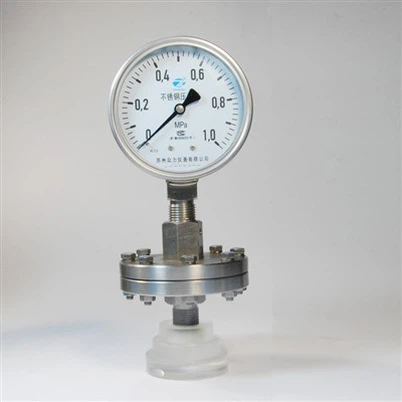
The zero point drift of a pressure gauge, in essence, means that when the pressure gauge is absolutely free of all external pressure and only withstands ambient atmospheric pressure, its indicator pointer fails to accurately stay on the zero mark of the dial, but shows a continuous positive or negative deviation. This zero point is the datum starting point of instrument measurement, and any deviation of it means that the entire measurement coordinate system has been translated. Therefore, zero-point drift does not only affect the zero-point reading, but will be superimposed on all measured values within the entire range of the instrument with a fixed deviation, causing all readings to be systematically higher or lower, causing the instrument to lose its due measurement accuracy.
What is the underlying cause of zero point drift?
The root cause of the zero point drift of a pressure gauge often involves changes in the physical properties of its internal structural materials, wear and tear of mechanical components, and the complex effects of external environmental factors.
First of all, elastic components such as Bourdon tubes, diaphragms or bellows will undergo microstructural changes after being subjected to cyclic pressure loads for a long time, resulting in their inability to fully return to their original geometric shape after the pressure is completely removed, which directly leads to the offset of the zero point.
Secondly, friction or vibration during long-term operation will cause the shaft hole clearance of the transmission amplification mechanism to increase and the gear mesh to generate tooth side clearance, making it impossible to accurately amplify the small displacement of the elastic element and transmit it to the pointer.
Furthermore, components made of different materials inside the instrument (elastic components, transmission connecting rods, support structures, etc.) have different thermal expansion coefficients. When the ambient temperature changes, their respective dimensions change inconsistently. This differential expansion or contraction will be transmitted to the pointer through the transmission chain, causing the zero point reading to fluctuate with temperature.
In addition, improper stress exerted during the installation process, such as over-tightening interface threads, may cause slight deformation of the case or internal base, thereby affecting the alignment accuracy of the internal movement and inducing zero-point drift.
The consequences of pressure gauge zero point drift are often not just simple inaccurate readings, but may form a series of potential chain reactions. In an automated control system, if the control loop is adjusted based on a pressure signal with zero point drift, then this inherent deviation will be continuously "compensated" by the system, causing the actual working pressure to deviate from the optimal set point for a long time. This may not only reduce the product qualification rate and increase energy consumption, but may also cause side reactions or change the reaction path in some chemical reactions.
At the safety level, zero-point drift will make the originally set safety range unreliable. For example, a pressure gauge with a low display (negative drift) may cause the operator to still think that the pressure is still in a safe zone when the system approaches or reaches a dangerous pressure limit (such as the maximum allowable working pressure MAWP of the vessel), thus delaying the necessary pressure relief or emergency shutdown measures; conversely, a display with a A pressure gauge with a high indication (positive drift) may cause the system to frequently trigger alarms or protective actions well before it reaches the actual dangerous pressure, affecting production continuity, or causing operators to habitually operate equipment at a higher real pressure than the design allows, accelerating equipment aging and even posing accident risks.


Detecting the zero point drift of the pressure gauge requires standardized operating procedures and reliable reference standards. First of all, it is necessary to ensure that the connection end of the pressure gauge is completely isolated from the pressure source and is completely vented to the atmosphere through a drain valve or disconnection to ensure that there is no residual pressure inside. After waiting enough time for the pointer to stabilize, carefully observe whether it is accurately aligned with the zero mark.
In order to quantitatively evaluate the drift and eliminate subjective judgment errors, it can be compared in parallel with a digital pressure gauge, precision pressure gauge or piston pressure gauge (pressure calibrator) with a higher accuracy level and within a valid calibration period. In order to more comprehensively evaluate the status of the instrument, you can continue to select several pressure points within the range (such as 25%, 50%, 75%, 100% F.S.) for comparison. This will help distinguish zero point drift, linearity error or indication error.
How to systematically correct the zero point drift of a pressure gauge?
Systematically correcting the zero point drift of a pressure gauge requires selecting an appropriate method based on the degree and cause of the drift, as well as the design of the instrument itself.
For only minor zero point drift and the instrument is designed with an external zero point adjustment mechanism (usually a small screw on the dial or a rotatable outer ring of the watch cover), standard external zero point fine-tuning operations can be performed. The premise is that after confirming that the instrument is completely in a zero-pressure state, use a special tool to gently and slowly rotate the adjustment device until the pointer is accurately aligned with the zero position. This adjustment is mainly used to compensate for small natural drifts caused by small fluctuations in ambient temperature or long-term use. It is usually ineffective for larger drifts caused by severe deformation or wear, and forced large adjustments may damage the internal mechanism.
If the external adjustment cannot correct the zero point, or the calibration finds that in addition to the zero point error, other range points also have out-of-tolerance, then multi-point calibration and internal adjustment must be performed. This requires professional metrology technicians to use a precision pressure standard under a standard environment and follow the calibration procedures to measure the actual error at multiple pressure points including the zero point. According to the error distribution, open the watch case and make fine adjustments to the internal transmission mechanism, such as adjusting the meshing position of the sector gear and the center gear, changing the effective length of the connecting rod, adjusting the pre-tightening force of the hairspring, etc.