How to install a pressure gauge for optimal performance
Leave a message

Pressure gauges play a key role in monitoring pressure status and ensuring the safe operation of equipment in industrial systems. However, many users find that the pressure gauge has inaccurate readings, short lifespan, and even sudden failures during use. These problems are often caused by negligence in the installation process. An improperly installed pressure gauge not only fails to reflect the true pressure, but may even cause equipment abnormalities or safety accidents. This article will systematically explain the installation details of the pressure gauge from site selection, structure, connection, etc., to help users install the pressure gauge correctly.
The installation location should avoid interference sources
Whether the reading of the pressure gauge is accurate and stable fundamentally depends on whether its location is reasonable, because the working principle of the pressure gauge is to deform in response to pressure changes through internal elastic components (such as Bourdon tubes), and then reflect the readings through the mechanical transmission structure.
If a pressure gauge is installed on a steam pipe, close to a valve or heat source, it may be exposed to temperatures exceeding 100°C or even higher in a short period of time. Such high temperature will cause the elastic modulus of metal to decrease at high temperature, weaken the deformation response, and reduce the sensitivity of the Bourdon tube, causing the pointer to respond slowly or even not return to zero. Over time, thermal fatigue will cause the bourdon tube to permanently deform and cause "zero point drift", and the pointer will not be able to return to the zero position even in a no-pressure state. In addition, most pressure gauges have a closed structure, and high temperatures will heat the air inside the gauge, causing it to expand and form additional internal pressure. This "fake pressure" is superimposed on the real measurement, causing the reading to always be too high.
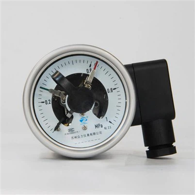
When the pressure gauge is installed at the pump outlet or on a mechanical structure that vibrates frequently, such as a centrifugal pump, an electric valve or a compressor, the mechanical vibrations generated by these devices at the moment of startup or shutdown will be directly transmitted to the gauge body through the pipeline. The pressure gauge is a precision instrument. The internal linkage, gears, hairspring and other components are closely coordinated. Continuous vibration will cause the pointer to keep shaking even when the pressure is constant, resulting in blurred and unreadable readings.
The Installation Direction Must Be Vertical
Most mechanical pressure gauges are designed to be installed vertically because their internal structures (such as hairsprings, gear sets, and Bourdon tubes) can achieve force balance in the vertical direction. If the instrument is tilted during installation, gravity will cause the gear mesh to be out of alignment and the hairspring to be unevenly stressed, causing the pointer to shift and distort the reading.
In some actual projects, in order to cooperate with the horizontal pipeline, the operator often screws the pressure gauge directly into the side-mounted interface without correcting it, causing the gauge to tilt upward, downward or even horizontally. This not only causes inaccurate readings, but also easily causes problems such as gauge needle sticking due to the offset of the lubricating oil in the gauge and the bias of the glycerin gauge bubble.
The correct approach should be to use 90° elbows, extension pipes, spiral pipes and other joints to turn the meter so that the dial always faces the operator and remains vertically upward. After the installation is complete, use a level or laser vertical line to calibrate the angle to ensure that the gravity axis of the entire meter is strictly aligned with the force direction of the gear.
As a precision mechanical instrument, the case of a pressure gauge is not designed to withstand external forces, but is only used to encapsulate and protect the internal mechanism. Therefore, the force application point is never allowed to be directly added to the case body during the installation process; however, during on-site installation, some operators, to save trouble or because the tools do not match, The watch case will be clamped directly with a pipe wrench and tightened. This method can easily cause the outer wall of the watch case to be crushed or cracked. The more serious problem is that when external strong force acts on the watch case, the support relationship between the watch core and the watch case will be offset, causing the instrument to be unable to be reset or a "dead needle" phenomenon will occur.
In addition, if you do not use a special installation wrench to tighten the hexagonal joint at the bottom of the pressure gauge during the tightening process, but forcefully rotate it through a soft joint or bare hands, it is easy to cause the connecting thread to be sprained, deformed or even cross-threaded, which will affect subsequent sealing.


And even if the correct tool is used, if the appropriate torque standard is not mastered, it may still cause problems: if it is tightened too loosely, the sealing ring cannot be fully compressed, and micro-leakage will occur during use, which not only causes the loss of the medium, but may also cause safety accidents under high-pressure or toxic conditions; and if the force is too strong, the welding seat, flange or meter body structure at the bottom of the pressure gauge may be cracked.
Therefore, in actual installation, a special wrench must be used to match the thread size, correctly act on the hexagonal joint, and control the tightening force to ensure tightening without imposing additional stress on the pressure gauge body.
There are many types of pressure gauge connection threads, such as R thread, G thread, NPT, etc. Different threads require different sealing methods. If the connection method is incorrect, it may cause leakage or air bubbles to enter, interfering with pressure transmission.
For example, tapered threads (such as R threads) require a sealing tape to be wrapped around the thread; while flat threads (such as G threads) require a metal gasket or rubber sealing ring to be sealed at the end face. Wrong matching not only results in poor sealing, but also causes uneven axial stress during installation, leading to connection failure. Therefore, it is necessary to find out the thread specifications before installation and select the sealing material according to the instructions. It cannot be handled hastily based on experience.